3 Input Xor Gate Circuit Diagram
Gates using xor gate inputs not schematic only into input logic circuit digital building where but combined circuitlab created stack Xor gate ic input quad circuits four gates exor digital Digital logic
Xor Logic Gate Circuit Diagram : 1 - The output is 'low' if both the
3 input xor gate Vhdl tutorial – 5: design, simulate and verify nand, nor, xor and xnor Quad xor gate ic with common input to all four gates? : electronic_circuits
Xor nand logic nor gates xnor circuit vhdl simulate verify truth input circuits tutorial engineersgarage inverter scosche inputs ckt combined
Vlsi xor xnor nor nand vlabs iitg inputsXor logic gate circuit diagram : 1 Figure 1 from high efficient 3-input xor for low-voltage low-power highCircuit diagram of xor gate.
Xor gate inputXor gate circuit diagram transistor sponsored links .

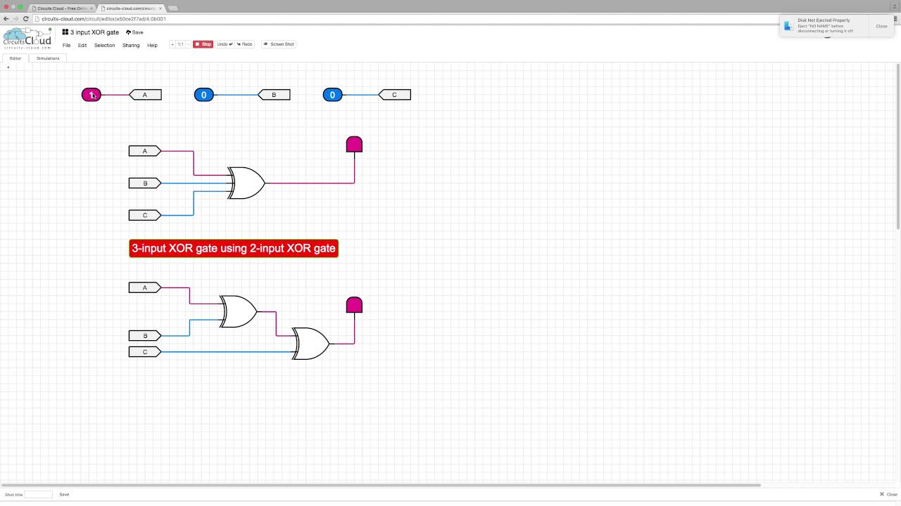
3 input XOR gate - YouTube

Circuit Diagram Of Xor Gate

Quad XOR gate IC with common input to all four gates? : electronic_circuits

digital logic - Building a XOR gate on 3 inputs using only 5 AND/OR/NOT

VHDL Tutorial – 5: Design, simulate and verify NAND, NOR, XOR and XNOR

Figure 1 from High efficient 3-input XOR for low-voltage low-power high